
This is the first in a series of blog posts intended to journal my progress through the COMP444: Embedded Robotics course with Athabasca University. These blogposts will serve to track my progress through the readings, questions, assignments and exercises that I will be completing throughout this course. I will try to add additional how-to information that might assist other learners, and I will track development of my own Arduino projects acress these pages.
# Resources
For this blog post the following items will be most helpful:
- An understanding of the history of the arduino project: https://en.wikipedia.org/wiki/Arduino
- The Sparkfun Inventor’s Kit: https://www.sparkfun.com/products/15267
- The Arduino Development Environment(I’m going to be using Arduino IDE 2.0 beta): https://www.arduino.cc/en/software
- Documentation for using the Arduino IDE 2.0 beta:https://docs.arduino.cc/software/ide-v2
- The Robotics Primer: https://mitpress.mit.edu/books/robotics-primer
- The Robotics Primer Workbook: http://roboticsprimer.sourceforge.net/wiki/index.php/Main_Page
- The Instructor’s Notebook: https://landing.athabascau.ca/file/download/3025749
# The SparkFun Inventor’s Kit
I’ll begin by exploring the SparkFun Inventor’s Kit (SIK). The SIK comes in a nice hardshell case, as shown below.

After opening and unwrapping the various components included in the kit I have found that it is composed of the following items:
- SIK Guidebook Version 1.4a https://github.com/sparkfun/SIK_Guide/raw/master/English/SIK%20v4.1%20Book%202019%20WEB.pdf
- SparkFun RedBoard Qwiic
- BreadBoard
- Baseplate for Breadboard and RedBoard
- Flathead Screwdriver
- LCD Display
- 2 x Rubber wheels
- 2 x 48:1 Geared Motors
- Motor Driver Breakout board
- MicroServo
- Small gears for the MicroServo
- Various Resistors
- Various LED’s
- 4x Colored Buttons
- Jumper wires
- Micro-USB cable
- Battery Container
- Velcro Strip
- Trimpot
- Temperature Sensor
- Mini Speaker
- Mini Power Switch
- Photocell
- Binder Clip
- Ultrasonic Distance Sensor

# Setting Up the IDE
The install process for the Arduino IDE is fairly straight forward. Go to the Arduino website and download the IDE you wish to install, I am using 2.0.0-beat.11. Here is a direct link to the appropriate download for windows: https://downloads.arduino.cc/arduino-ide/arduino-ide_2.0.0-beta.11_Windows_64bit.exe Once you have downloaded your IDE, locate your download and run through the guided installation process.
Once the IDE is installed we still need some specific drivers for the RedBoard Qwiic. You can grab the drivers from: https://cdn.sparkfun.com/assets/learn_tutorials/8/4/4/CH341SER.EXE. Once they are downloaded, locate your downlad and run through the installer.
At this point we can use the microUSB cable to plug the RedBoard into your computer. You should see some lights on the board activate and hear a ding from windows as the device is connected.
We need to grab some code specific to the SIK from the following link: https://github.com/sparkfun/SIK-Guide-Code/archive/master.zip. We need to extract the contents of the zip file into to the examples subfolder. Based on the default installation options this folder should be located at: C:\Users\%USERNAME%\OneDrive\Documents\Arduino\Examples
Next we need to open the Arduino IDE, and establish a connection to our RedBoard. Once you have loaded into the IDE, at the top select Tools > Board > Boards Manager... The 2.0 IDE does not come preset to work with any boards so we have to add the UNO before we can connect to our RedBoard. In the Boards manager search for Uno Then install the Arduino AVR Boards by Arduino. You can now select the Uno board Tools > Board > Arduino AVR Boards > Arduino Uno
We next need to determine which port our RedBoard Qwiic is on so that we can set that in the IDE. Open up Windows Device Manager, ( I like to get there with “win + x”. Expand the Ports (COM & LPT) section. You need to find USB-SERIAL CH340 (COMXX) Note what COM number is associated with your CH340 device. Now go back to the IDE and select Tools > Port > COMXX Where COMxx matches the value you found in the device manager.
At this point we should be set up and ready to work with your RedBoard. You can now attempt to verify your code, and then you can press the upload button. If everything is working properly, you should see a couple of led’s flicker on the Redboard, and the output section or the IDE should read:
Sketch uses 444 bytes (1%) of program storage space. Maximum is 32256 bytes.
Global variables use 9 bytes (0%) of dynamic memory, leaving 2039 bytes for local variables. Maximum is 2048 bytes.

--------------------------
Compilation complete.

--------------------------
upload complete.
Congratulations, you are now ready to get started with the course.
Shawn Ritter
October 4th, 2021
# SIK Project 1A
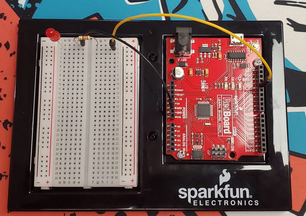
After reviewing the instructor’s notebook, it looks like we are also supposed to complete a simple project from the SIK. In this project I will set up a simple circuit that will allow us to blink an LED using the RedBoard. This will give us a chance to test the IDE and make sure that everything is working correctly. This will also give us experience in verifying and uploading code to the RedBoard.

SIK v4.1 Guidebook Pg. 15 – Circuit Diagram
Here’s a picture of what the circuit looks like when it’s set up on the board.
In the Arduino IDE we then use the following code to blink the LED. It will turn on for two Seconds, and then off for 2 seconds in an infinitely repeating loop.
void setup() {
  pinMode(13, OUTPUT);      // Set pin 13 to output
}

void loop() {
  digitalWrite(13, HIGH);   // Turn on the LED

  delay(2000);              // Wait for two seconds

  digitalWrite(13, LOW);    // Turn off the LED

  delay(2000);              // Wait for two seconds
}
There are two main functions in any Arduino project, the setup() and loop() functions. Inside the setup() function, we set pin D13 to be an output. Then we can move into the loop() where we will turn on the LED for 2000 milliseconds, followed by us turning off the LED for 2000 milliseconds.
Shawn Ritter October 6th, 2021