In this entry I will be working through the material for Unit 2 of COMP444 Embedded/robotic programming. I will begin with the readings of chapters 4 and 5 in the textbook, and their food for thought questions. Then I will work through the SIK circuits 8-13 or projects 3 and 4 Motion and Display. Finally I will spend some time on the companion workbook for the text in a section called locomotion.
Table of Contents
- Reading – Chapter 4: Arms, Legs, Wheels, Tracks, and What Really Drives Them
- Reading – Chapter 5: Move It!
- Project 3: Motion
- Circuit 3A: Servo Motors
- Circuit 3B: Distance Sensor
- Circuit 3C: Motion Alarm
- Project 4: Display
- Circuit 4A: LCD “Hello World”
- Circuit 4B: Temperature Sensor
- Circuit 4C: “DIY Who Am I?” Game
- Robotics Primer Workbook – Locomotion
- Conclusion
Reading – Chapter 4: Arms, Legs, Wheels, Tracks, and What Really Drives Them
This chapter seems to be very closely related to the Robot Components section from the workbook. It discusses the differences between effectors and actuators, and it breaks down the relationship between controllable degrees of freedom and total degrees of freedom.
- How would you measure a motor’s torque? What about its speed?
“When the motor is spinning freely, with nothing attached to its shaft, then its rotational velocity is the highest, but the torque is zero. The output power, then is also 0. In contrast, when the motor is stalled, its torque is the maximum it can produce but the rotational velocity is zero, so the output power is again zero. Between these extremes of free spinning and stalling, the motor actually does useful work and drives things efficiently.”
The Robotics Primer. Maja J Mataric. P 34
Torque is a measure of the force a motor can produce, while speed is the measurement of the the revolutions produced in a given time, typically in rpms. So to measure torque you would find the point at which the motor stalls when a resistance is applied. By calculating the force that causes a stall it should be possible to determine the force that the motor can create. However adjusting the current to an electric motor should affect the torque available, but may affect the wear on the motor.
Speed is usually measured in displacement or distance over time, but for an electric motor I believe that it typically refers to the rotations in a given time. So typically speed would be measured as the RPM’s of a motor.
- How many DOF are there in the human hand?
Each finger can curl to close, and can be moved side to side a little, the thumb has additional movement. In a very simple sense then, I would say that the hand has 11 DOF, based on two DOF for each finger and three for the thumb. However, this is an incomplete assessment. as each finger actually has 3 joints and not just one. So That means that each finger now has four DOF, while the thumb has five. This brings us to 21 DOF in the hand. Lastly we can also consider the wrist as it is important for the dexterity of the human hand. The wrist can bend forwards and backwards, flex from side to side and rotate adding a further 6 DOF to the hand. Altogether that means that the human hand can be said to have 27 degrees of freedom. More details on why this is the case can be found here: http://www.dgp.toronto.edu/~gelkoura/noback/scapaper03.pdf.
Reading – Chapter 5: Move It!
This chapter deals with the logistics of movement. What types of motion systems are used in robotics and in nature and how the number of legs affects the center of gravity or stability of the motion system.
- How does an automated Web Path planner, such as google maps find the optimal path for a trip?
From what I understand, Google maps looks at your beginning location and your ending location. It then looks at the various roads that are between these two points and scores each road based upon a number of factors, including distance, speed and traffic conditions. Google then uses an algorithm to select the highest scoring path and present it as the optimal route. For longer range routes I believe that google essentially uses nodes, and then uses a similiar process to map the optimal route from one node to the next until the entire path is mapped out.
Project 3: Motion
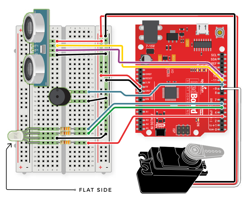
So the instructor’s notebook for unit 2 indicates that we should complete circuits 8-12 this week. With the revisions to the SIK these numbers no longer line up. As such I believe that completing projects 3 and 4 or circuits 8-13 will be adequate, then with Unit 3 I will complete the final Project and circuits 13-15. Project 3 will look into how to use servo motors and an ultrasonic distance sensor to create a motion alarm.
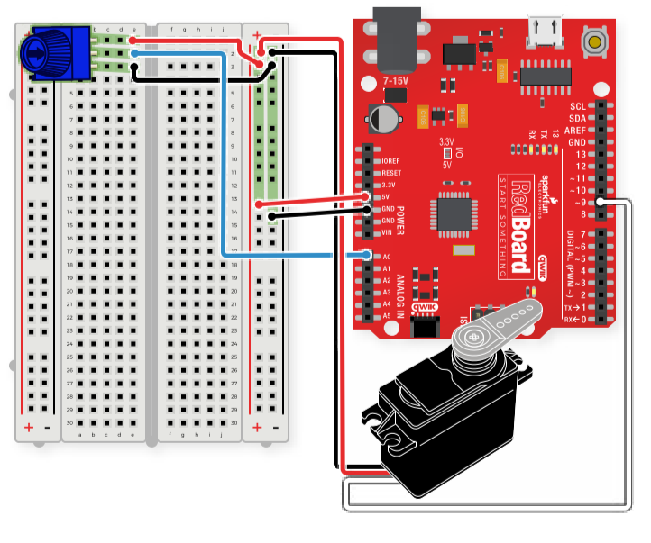
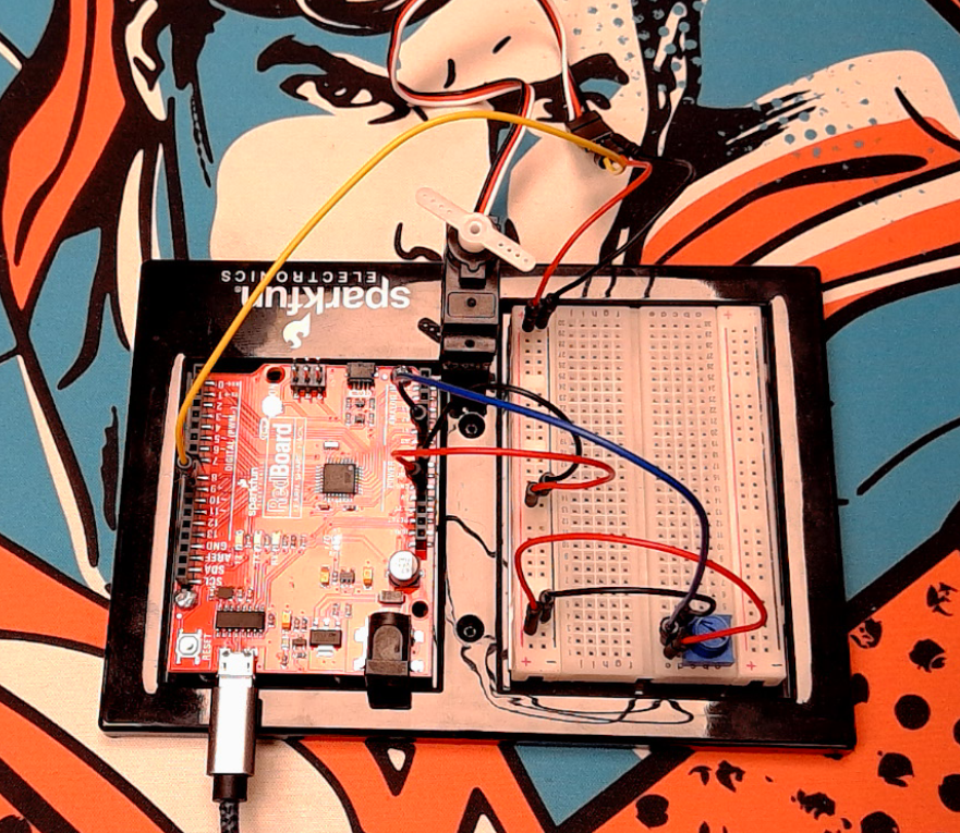
Circuit 3A: Servo Motors
This circuit is intended to introduce the use of a servo motor for arduino projects. I ran into a problem when attempting to verify and compile the code for this project. I believe the problem was caused as I was using the Arduino 2.0.0 IDE. By switching ack to Arduino 1.8.16, everything was able to compile correctly and without error. I believe this is due to how the IDE 2.0 handles libraries, I tried testing with a few libraries from the library manager, but ultimately it was easier to just switch back to the earlier IDE.
Here is the Wiring Diagram:
Circuit 3B: Distance Sensor
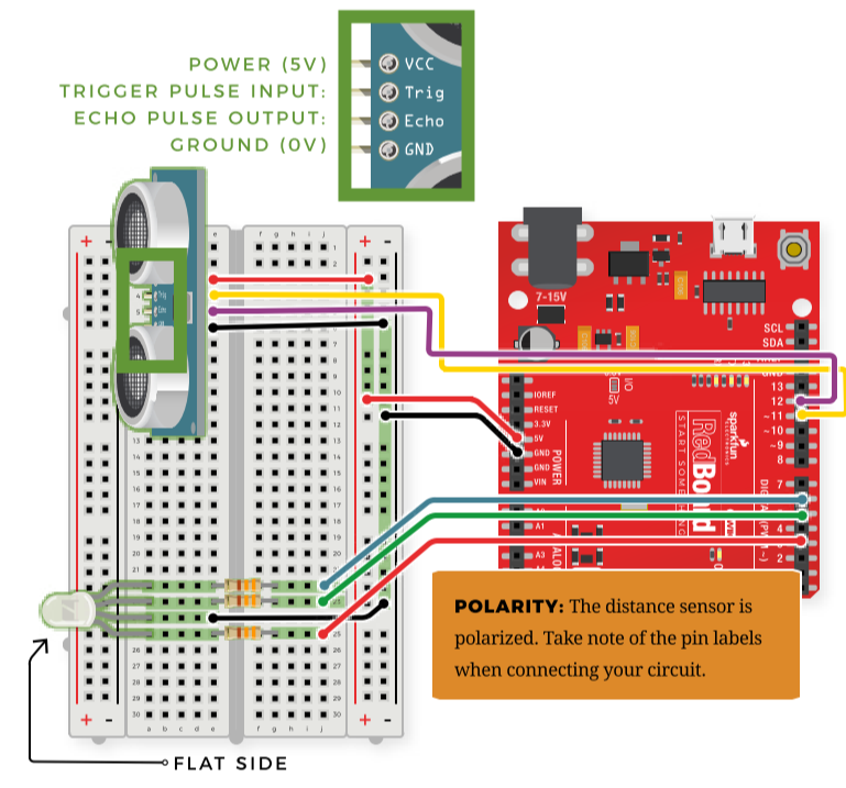
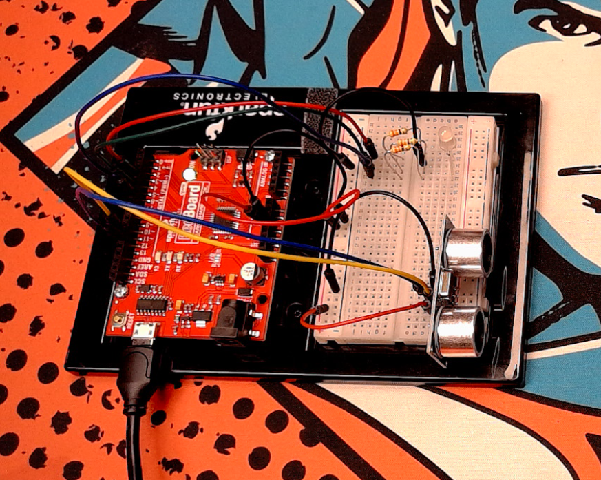
This circuit uses an ultrasonic distance sensor to light up an RGB led based upon the distance that is measured by the sensor.
Circuit 3C: Motion Alarm
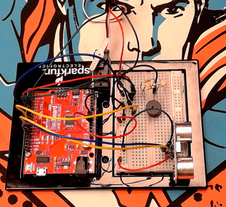
This circuit combines the previous two to create an alarm that indicates the distance of an object with an LED and if an object gets too close a buzzer is sounded and the servo activates to create some motion.
Project 4: Display
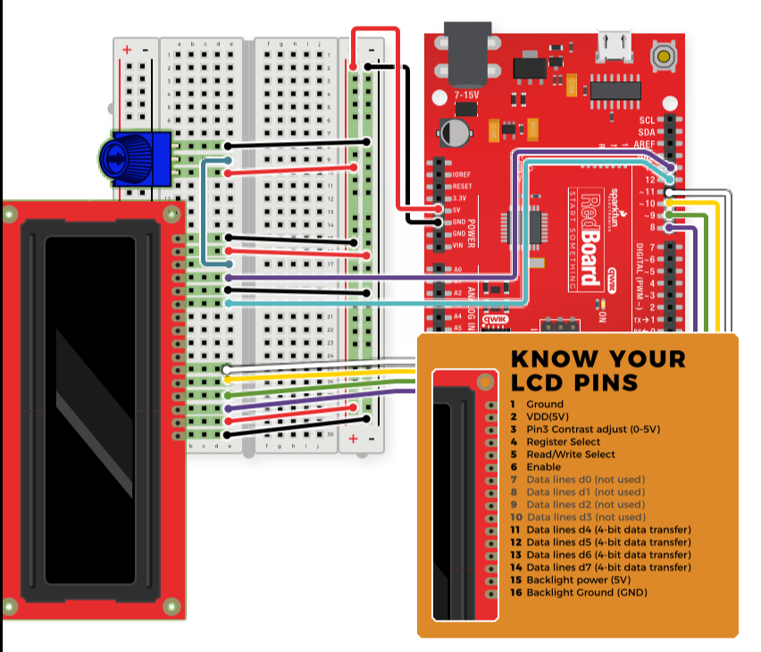
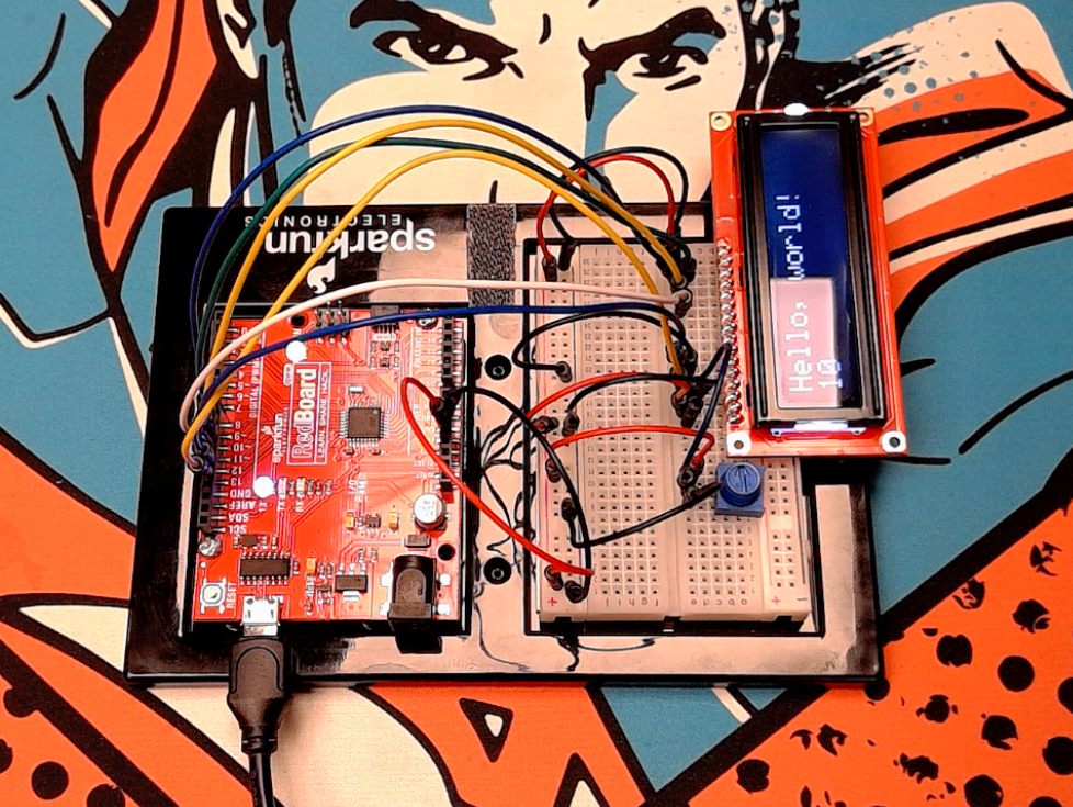
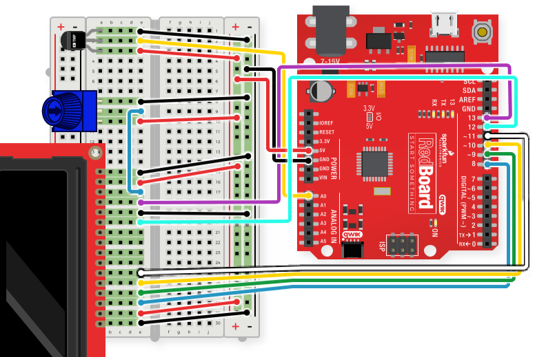
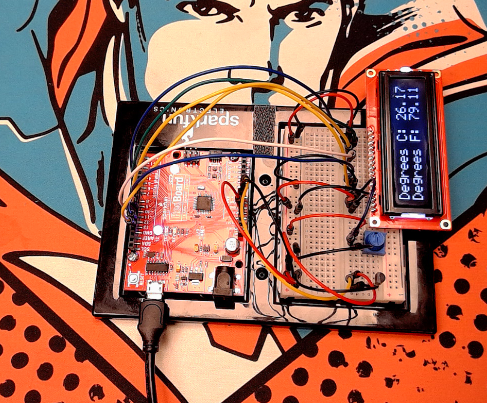
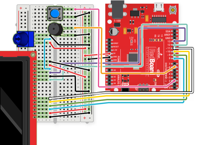
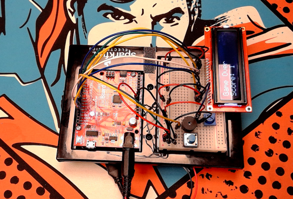
This project is all about using an LCD display to show information. The first circuit displays a string of characters and a counter. The second displays data from a sensor, and the final circuit uses the display to run a simple game.
Circuit 4A: LCD “Hello World”
Circuit 4B: Temperature Sensor
Circuit 4C: “DIY Who Am I?” Game
Robotics Primer Workbook – Locomotion
The instructor’s notebook we are asked to go through the locomotion section of the workbook and answer the questions in this section. It will not be possible to complete the exercises, but we should be able to compare what they are doing with the iRoomba kit to our current SIK. A bit of time should be spent on comparing the iRoomba motors to the motors included in the SIK and finally we should discuss how we might build a similiar robot with the SIK. It will be important to note what additional parts will need to be purchased for this though.
Exercise 1 Locomotion and Odometry
This exercise uses the iRobot create kit and either the command module or Gumstix to move a robot in a square pattern. After setting up and running this exercise, the student is asked to speculate on why the path followed by the robot is not actually a perfect square? What is causing the error?
My speculation would be that there may be stalling or missteps as the motors start and stop. As the speed of the motor is changed the inertia of the robot has to be overcome, this results in greater current and torque needed as the robot starts or stops moving. If the control circuit can’t adapt to this, then there will be slippage and the position reported by the controller and the position actually occupied by the motor will differentiate from each other.
I do believe that there are enough parts in the SIK that we could attempt a similiar project, though we might need a third wheel to keep from dragging the board.
Exercise 2 Path Following
In this exercise two photoresistors are used to allow the robot to follow a black path on a white background.
This exercise poses the question of where would the optimal location be for the two photoresistors? Should they be placed on the front or the back, side by side or in front of each other, Should they be placed wide apart or close together? The question indicates that there is no one correct answer and that experimentation should be used to answer this question.
To approach this question we would need another photoresistor, some butcher paper and a sharpie or electrical tape to create the pathway. My initial thought would be that we should put the photoresistors in the front of the robot, behind each other and reasonably close together. My thinking is that the robot would be started on the line, and would move in such a way as to keep the sensors on the black line. If the forward sensor was reporting a bright backgorund the robot would wiggle till it found the black line again.
Exercise 3 Homing
For this exercise the robot is set up so that it can home toward a bright light in its environment. In this example, there are two receptors placed forward on the front of the robot and fairly wide apart. There is no actual question posed in this section and the work seems to focus in on determining what sensor values should be used for driving the robot and stopping it at a reasonable distance.
Exercise 4 Teleoperation
In this exercise the robot is controlled remotely from a GUI terminal. We could attempt to do something like this by adding a radio module to the SIK or by trying to use a longer usb connection. Depending on how the GUI is set up it could be quite challenging to accurately control the robot. However, optimally I think this would be no different than controlling an RC vehicle, and the biggest issue for control would be from observing the location and position of the vehicle/robot from a distance.
Exercise 5 Holonomic and Nonholonomic Control
This section asks three questions and doesn’t have a project in this section.
- Explain the difference between holonomic and non-holonomic robots.
This was discussed in the text and holonomic control is when the controllable degrees of freedom are equal to the total degrees of freedom of the robot. If the controllable degrees of freedom are less than the total degrees of freedom of the robot then the robot is said to be nonholonomic.
- What type of control does the create possess Holonomic or non holonomic? (In this case the SIK)
The create robot is kind of like a car, it can turn and go forwards or backwards, but it cannot move side to side or laterally. If we were to use the two motors and wheels in the SIK we would face the same limitations. This is nonholonomic control.
- How would holonomic control of the robot make things harder/easier for the previous exercises?
The implementation of the controller logic would be more difficult, but some movements would be easier. The robot would likely have an easier time finding and following the line with full holonomic control, but the implementation would be more complex.
Conclusion
That concludes my comments and exploration of Unit 2.
Shawn Ritter
October 9th, 2021
Featured Image: https://www.thatmomentin.com/3-things-worse-about-wild-wild-west-than-an-80ft-mechanical-spider/

