This blog entry will deal with an introduction to robots, their history, terminology and a few introductory projects with the SIK. I this entry I will be looking at the first three chapters in the textbook “The Robotics Primer”, where I will add a few notes from each chapter as well as my reflections on the “Food for Thought” questions in each chapter. I will then finish up by working through some exercises with the SIK and will document my experience.
This post has gotten rather large, so I wanted to add a table of contents that will allow you to jump down to the various sections. I begin with the readings from the Robotics Primer, then I spend some time working through the example circuits from the SIK. Lastly I take the time to work through the Robot Components section of the Robotics Primer Workbook.
Table of Contents
- Chapter 1: What is a Robot?
- Chapter 2: Where Do Robots Come From? A Brief but Gripping History of Robotics
- Chapter 3: What’s in a Robot? Robot Components
- Projects
- Circuit 1B: Potentiometer
- Circuit 1C: Photoresistor
- Circuit 1D: RGB Night-Light
- Project 2A: Buzzer
- Project 2B: Digital Trumpet
- Project 2C: “Simon Says” Game
- Robotics Primer Workbook – Robot Components
- Robotics Primer Workbook – Exercise 1: Sensors and Sensor Space
- Robotics Primer Workbook – Exercise 2: Effectors and Actuators
- Conclusion
Chapter 1: What is a Robot?
Humans have made use of tools and machines to achieve tasks throughout our history. What is it that sets a robot apart from the other machines or tools that we have developed? The text defines Robots as “an autonomous system which exists in the physical world, can sense its environment and can act on it to achieve some goals”. There are four key pieces of information here; robots are autonomous, they can operate without human interaction. Robots are physical creations, having presence in the physical world. Robots can sense their environment, they are able to receive input from their environment. Lastly, they can use that input to perform actions which allow them to affect themselves or their environment.
Food for Thought
- What else can we do from afar, by means of teleoperation? We can talk, write and see, as in telephone, telegraph, and television. There is more. Can you think of it?
One of the keys above is that robots are autonomous, they do not require control inputs to achieve their tasks. Teleoperation or remote control has been around for a long time and has allowed us to create many things that have the appearance of being a robot, without actually functioning as a robot. I believe that some of the earliest teleoperation examples that made use of wireless technology or were remote controlled, were developed by Nikola Tesla, and displayed in 1898 to remote control boats (https://science.howstuffworks.com/innovation/repurposed-inventions/history-of-remote-control.htm). Since then we have used remote control for many purposes, such as drones that are used for reconnaissance. However there has been a push for the development of autonomous machines that are intended to replace, or upgrade these drones. An interesting technology that is currently making progress is the development of self-driving cars. Historically there has been a need for an operator to control the vehicle, but great progress has been made and is ongoin in making vehicles that would qualify as being a full fledged robot.
- Is a thermostat a robot?
In the definition of a robot above, I do believe that a thermostat is a robot. It exists in physical space, it has a sensor, and a goal or a temperature set point. It is able to affect the environment by turning on or off a heater or cooler in order to achieve its goal. It is a simple feedback system, but it is a vital tool for most homes and businesses. Lastly, it can operate without needing human intervention, the initial setpoint is chosen and away it goes.
- Is a toaster a robot?
While a toaster is in some ways similar to the thermostat we discussed, I would not consider a toaster to be a robot by our current definition. This is due to the importance of autonomous in our definition. Most toasters do not have a sensor that indicates the presence of bread and cannot function without an operator turning on the machine.
- Some intelligent programs, also called software agents such as Web crawlers are called “softbots”. Are they robots?
By the definition given in the text, softbots would not qualify as robots as they do not exist in the real world.
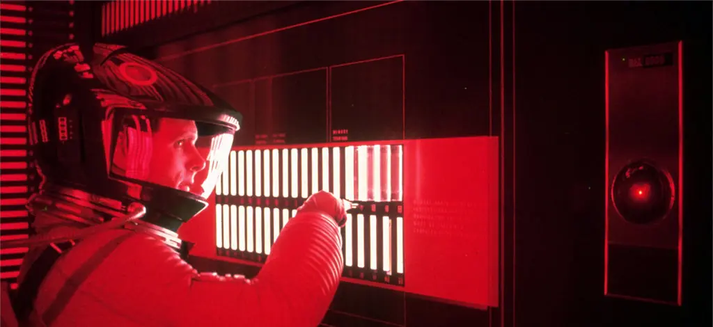
- Is HAL, from the movie 2001 the space odyssey, a robot?
Yes and no. First of all HAL is fictional and does not exist in our world in a meaningful or realized way. So on that account HAL is not a robot. However, within the universe and world that is established in the movie, HAL would qualify as a robot. HAL is able to operate autonomously. HAL is physically represented and embodied by the spaceship that contains it, and HAL is able to use the sensors in that spaceship to gain input from its environment. In many ways HAL is the spaceship, and the spaceship is HAL. Without HAL the spaceship would not be able to carry out its functions. Using the various machines, tools and equipment that compose the spaceship HAL is able to affect its environment to pursue its goals.

Chapter 2: Where Do Robots Come From? A Brief but Gripping History of Robotics
Robotics is a fairly young discipline, though some of the ideas that are foundational to robotics have been around for a very long time. Robotics as a field grew out of the ideas of control theory and cybernetics, the development of robotics occured in tandem with the field of artificial intelligence. The two fields have not always overlapped however, and the two disciplines are unique, in that artificial intelligence poses the question of thought, while robotics is more focused on the action. While clever machines have been built throughout the ages, it was only in the 1940’s that robots first began to be developed. The first machines that are considered by modern definition to be robots were the tortoise’s of Dr. W Grey Walters.
The field of robotics has progressed rapidly since the days of Grey Walters Tortoises, and by working with the field of artificial intelligence great strides have been achieved and the promise, or terrror of robotics continues to grow.
Food for Thought:
- How important is it for robots to be inspired by biological system?
Robotics is primarily about creating a physical object that can affect itself, or the world around it to pursue a goal. In many instances the process of achieving that goal may have already been solved previously by nature. When we look at how living creatures can impact and interact with their environment, we can see that nature has developed numerous ways to do many different things. If the fundamental problem we are facing is an engineering problem, I do believe that there are many lessons that we can learn from nature, however, we have the advantage of being able to collaborate and iterate. We can begin with a natural approach, and then find novel solutions that would never have bee possible in nature and which may be better options for applying our technology and understanding.
- Does it matter what kind of robot you are building? (Biomimetic or not)
If you are building a biomimetic robot, you have some references available to you in nature, but that also comes with constraints. Those constraints might mean that a current technology is not able to emulate the biological system without significant engineering. A robot can be built to emulate biological systems, but I believe the best solutions will combine an understanding of nature with modern technology to work around constraints and unlock even greater potential.
- Does it matter if it is going to interact with people?
Robots human interaction is a very large topic, with a lot of active research. I would not personally say that we need to use biomimetics for such a system, but there is a point where we need to be careful about our creations in order for humans to be willing to interact with them. There is a very real problem known as the uncanny valley, where the responsiveness of a human to an object is affected by how much that object bears a resemblance of a human. Stylized or abstract representations can be warmly received, but at a certain point where the likeness becomes close but not quite right there is a deep drop in receptivness. Indeed this drop can be so great as to invoke a revulsion even.

There is some very interesting work being done in this area, and I remember reading a story about how some robotics companies have had better luck engaging with users by creating a robot that has a screen with an animated smiley face for regular interactions with hotel guests than by trying to create a replica of a human. A quick google search for robotics and the uncanny valley will give you a lot of interesting reading material on the subject.
Chapter 3: What’s in a Robot? Robot Components
In our definition of robots, we said that a robot physically exists, and based on input from the world can perform actions to accomplish a goal. This means that robots are composed of parts that exist and interact. There are sensors that obtain input from the environment, there are effectors and actuators that allow the robot to interact with the world, and there is a controller which allows the robot to process input and drive output or action.
Food for Thought:
- What do you think is more difficult, manipulation or mobility? Think about how those abilities develop in babies, children and adults.
I think both are challenging, a baby might first start by picking up then chewing on blocks and toys. Later they will learn to walk and run. Later still they will learn to write. As they grow they might also take up a sport which requires movement and manipulation. I would say that both manipulation and movement are challenging. They both require time practice and skill to learn and master. Both are dependent upon an understanding of one’s body and capabilities as well as sensing the environment and understanding how one desires to impact or affect their environment.
- How large do you think your sensor space is
I think my sensor space is limited. I have a small scope within which I can operate and where I can maintain some sensory attention. Within that small space I can see, hear, smell, touch and taste which provides me with a multitude of input. But my senses have limited range, I can only see so far and in a very narrow strip of the electromagnetic spectrum some shrimp can see orders of magnitude more wavelengths than I. Many animals have more scent receptors or greater hearing than we as people. I would say that our sensory space is limited.
- Can you think of things or information in your life that is observable, partially observable, or hidden?
Yes. There are some things I can observe right now with the input I have available to me. I can look at my hand or my desk and observe to the limits of my unaided resolving power to see details and information. I can observe inputs, such as data from my senses, or my conscious thoughts and feelings. I would however say that feeling are in some way only partially observable, I can feel happy or sad, and sometimes I can know why I feel that way, but other times I can’t observe or control what I feel. I would also say that memories are only partially observable, I can only ever revisit a memory from my experience, I can’t see things from another’s view of the same event, I can’t see things from outside of my perspective or position, though I can imagine and extrapolate. Lastly, there is a lot that is hidden from me, there is information that is not part of my system. The thoughts and feelings of others are hidden from me though I can learn some of it through their actions or words. Within my own body there are many hidden things that are important. I am not consciously aware of my heart rate or respiration, yet without them I would die. I would say that the conscious self is observable or partially hidden, while the unconscious self is hidden.
Projects
In the Instructor’s Notebook it is recommended that after completing the reading for this Unit, Circuits 2-7 should be completed. I believe that the Instructor’s notebook was written based on an earlier version of the SIK Guidebook, though circuit 1 seemed to line up as the blinking of an LED. I am going to complete the next six circuits in the guidebook below. These will be the following circuits:
- Circuit 1B: Potentiometer
- Circuit 1C: Photoresistor
- Circuit 1D: RGB Night-Light
- Circuit 2A: Buzzer
- Circuit 2B: Digital Trumpet
- Circuit 2C: “Simon Says” Game
The CIrcuits below are from the SparkFun Inventor’s Kit Guidebook version 4.1A. The guidebook is available at: https://github.com/sparkfun/SIK_Guide/raw/master/English/SIK%20v4.1%20Book%202019%20WEB.pdf
Circuit 1B: Potentiometer
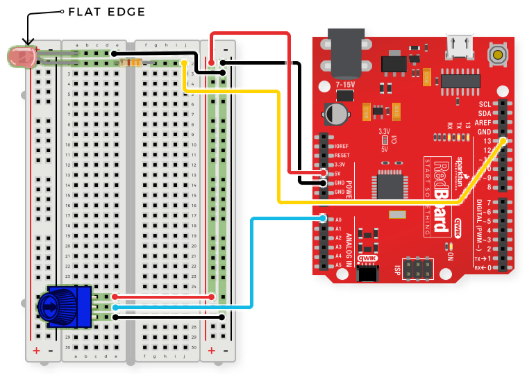
This circuit introduces the use of potentiometers, or trimpots. These allow the input of an analog signal that can be read by the RedBoard to affect behaviour. In this experiment we can control the speed of the blinking of the LED by adjusting the potentiometer.
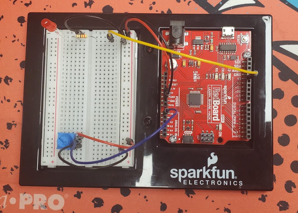
The Circuit Diagram is shown below, this is followed by a picture of the wired circuit. Notice that my breadboard has the positive and negative rails backwards to the diagram, so my wiring is very slightly different than expected.
Once we have wired up the circuit, we use the following code to bring the project to life:
/*
  SparkFun Inventor’s Kit
  Circuit 1B-Potentiometer
  Changes how fast an LED connected to pin 13 blinks, based on a potentiometer connected to pin A0
  This sketch was written by SparkFun Electronics, with lots of help from the Arduino community.
  This code is completely free for any use.
  View circuit diagram and instructions at: https://learn.sparkfun.com/tutorials/sparkfun-inventors-kit-experiment-guide---v41
  Download code at: https://github.com/sparkfun/SIK-Guide-Code
*/
int potPosition;       //this variable will hold a value based on the position of the potentiometer
void setup()
{
  Serial.begin(9600);       //start a serial connection with the computer
  pinMode(13, OUTPUT);      //set pin 13 as an output that can be set to HIGH or LOW
}
void loop()
{
  //read the position of the pot
  potPosition = analogRead(A0);    //set potPosition to a number between 0 and 1023 based on how far the knob is turned
  Serial.println(potPosition);     //print the value of potPosition in the serial monitor on the computer
  //change the LED blink speed based on the pot value
  digitalWrite(13, HIGH);           // Turn on the LED
  delay(potPosition);              // delay for as many milliseconds as potPosition (0-1023)
  digitalWrite(13, LOW);            // Turn off the LED
  delay(potPosition);              // delay for as many milliseconds as potPosition (0-1023)
}
The comments in the example code from the SIK Guidebook seem to be very clear. There are however a few new things in this solution that we should talk about. First of all this code makes use of an integer variable to store and pass the value of the potentiometer, this is the int potPosition; variable. Next, this solution uses the serial monitor to log information out from the RedBoard to the host computer. This is a valuable tool that allows us as developers to gain information about what is happening inside the RedBoard. The output/logging functions are handled by the “Serial” commands. The final thing I want to note is the use of the analogRead() function. This function allows us to obtain an value between 0-1023 from an analog input that can be used inside our program loop.
In the video it is interesting when the speed is set to be very fast that the light almost seems to do a gradual dimming down and up, while in person it is blinking at the same brightness very quickly.
Circuit 1C: Photoresistor
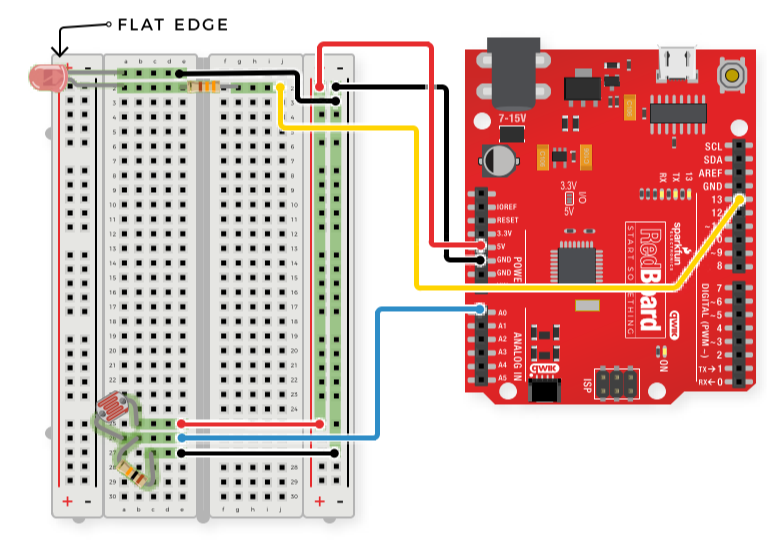
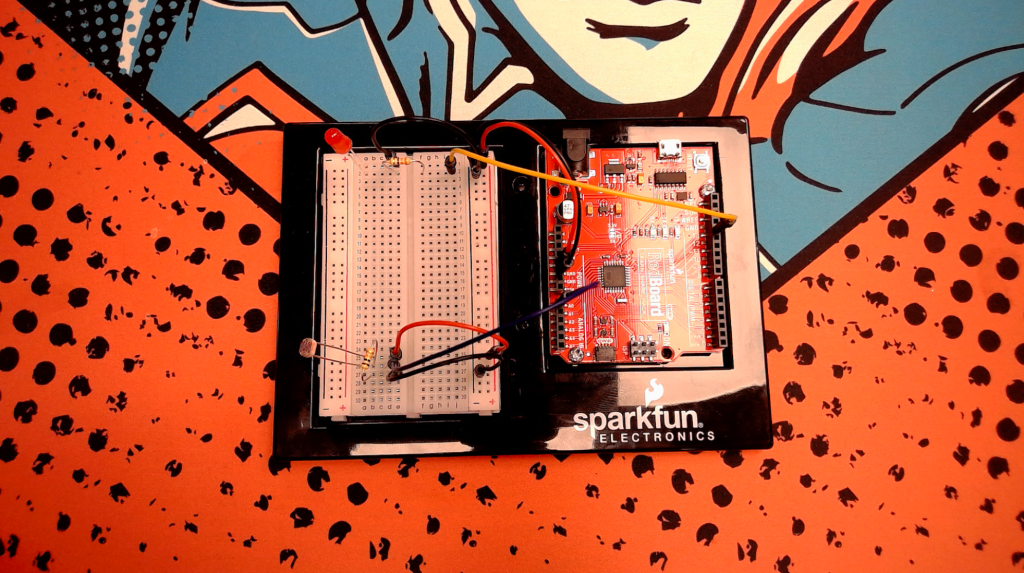
In this circuit, we are using input from a photoresistor to turn on an LED when the ambient light drops below a certain threshold.
/*
  SparkFun Inventor’s Kit
  Circuit 1C-Photoresistor
  Use a photoresistor to monitor how bright a room is, and turn an LED on when it gets dark.
  This sketch was written by SparkFun Electronics, with lots of help from the Arduino community.
  This code is completely free for any use.
  View circuit diagram and instructions at: https://learn.sparkfun.com/tutorials/sparkfun-inventors-kit-experiment-guide---v41
  Download drawings and code at: https://github.com/sparkfun/SIK-Guide-Code
*/
int photoresistor = 0;              //this variable will hold a value based on the brightness of the ambient light
int threshold = 750;                //if the photoresistor reading is below this value the the light will turn on
void setup()
{
  Serial.begin(9600);               //start a serial connection with the computer
  pinMode(13, OUTPUT);              //set pin 13 as an output that can be set to HIGH or LOW
}
void loop()
{
  //read the brightness of the ambient light
  photoresistor = analogRead(A0);   //set photoresistor to a number between 0 and 1023 based on how bright the ambient light is
  Serial.println(photoresistor);    //print the value of photoresistor in the serial monitor on the computer
  //if the photoresistor value is below the threshold turn the light on, otherwise turn it off
  if (photoresistor < threshold) {
    digitalWrite(13, HIGH);         // Turn on the LED
  } else {
    digitalWrite(13, LOW);          // Turn off the LED
  }
  delay(100);                       //short delay to make the printout easier to read
}
This code is fairly simple, with the only real addition from previous code being the use of logical statements and operators, such as the if else statement and the greater than evaluation. These logical operations are pretty standard in programming so I don’t have much to add here.
Circuit 1D: RGB Night-Light
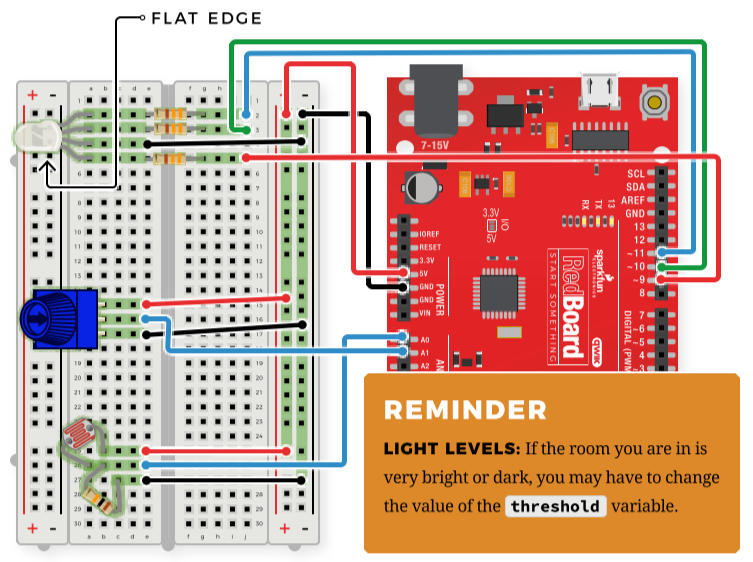
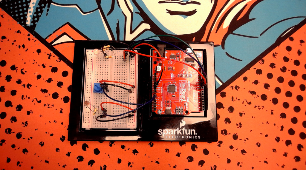
This project combines everything we have worked on so far, to create a multicolored nightlight. Using the trim-pot we can choose what colour the nightlight will display.
/*
  SparkFun Inventor’s Kit
  Circuit 1D-RGB Nightlight
  Turns an RGB LED on or off based on the light level read by a photoresistor.
  Change colors by turning the potentiometer.
  This sketch was written by SparkFun Electronics, with lots of help from the Arduino community.
  This code is completely free for any use.
  View circuit diagram and instructions at: https://learn.sparkfun.com/tutorials/sparkfun-inventors-kit-experiment-guide---v41
  Download drawings and code at: https://github.com/sparkfun/SIK-Guide-Code
*/
int photoresistor = A0;          //variable for storing the photoresistor value
int potentiometer = A1;          //this variable will hold a value based on the position of the knob
int threshold = 700;            //if the photoresistor reading is lower than this value the light will turn on
//LEDs are connected to these pins
int RedPin = 9;
int GreenPin = 10;
int BluePin = 11;
void setup() {
  Serial.begin(9600);           //start a serial connection with the computer
  //set the LED pins to output
  pinMode(RedPin, OUTPUT);
  pinMode(GreenPin, OUTPUT);
  pinMode(BluePin, OUTPUT);
}
void loop() {
  photoresistor = analogRead(A0);         //read the value of the photoresistor
  potentiometer = analogRead(A1);
  Serial.print("Photoresistor value:");
  Serial.print(photoresistor);          //print the photoresistor value to the serial monitor
  Serial.print("  Potentiometer value:");
  Serial.println(potentiometer);          //print the potentiometer value to the serial monitor
  if (photoresistor < threshold) {        //if it's dark (the photoresistor value is below the threshold) turn the LED on
    //These nested if statements check for a variety of ranges and
    //call different functions based on the current potentiometer value.
    //Those functions are found at the bottom of the sketch.
    if (potentiometer >= 0 && potentiometer <= 150)
      red();
    if (potentiometer > 150 && potentiometer <= 300)
      orange();
    if (potentiometer > 300 && potentiometer <= 450)
      yellow();
    if (potentiometer > 450 && potentiometer <= 600)
      green();
    if (potentiometer > 600 && potentiometer <= 750)
      cyan();
    if (potentiometer > 750 && potentiometer <= 900)
      blue();
    if (potentiometer > 900)
      magenta();
  }
  else {                                //if it isn't dark turn the LED off
    turnOff();                            //call the turn off function
  }
  delay(100);                             //short delay so that the printout is easier to read
}
void red () {
  //set the LED pins to values that make red
  analogWrite(RedPin, 100);
  analogWrite(GreenPin, 0);
  analogWrite(BluePin, 0);
}
void orange () {
  //set the LED pins to values that make orange
  analogWrite(RedPin, 100);
  analogWrite(GreenPin, 50);
  analogWrite(BluePin, 0);
}
void yellow () {
  //set the LED pins to values that make yellow
  analogWrite(RedPin, 100);
  analogWrite(GreenPin, 100);
  analogWrite(BluePin, 0);
}
void green () {
  //set the LED pins to values that make green
  analogWrite(RedPin, 0);
  analogWrite(GreenPin, 100);
  analogWrite(BluePin, 0);
}
void cyan () {
  //set the LED pins to values that make cyan
  analogWrite(RedPin, 0);
  analogWrite(GreenPin, 100);
  analogWrite(BluePin, 100);
}
void blue () {
  //set the LED pins to values that make blue
  analogWrite(RedPin, 0);
  analogWrite(GreenPin, 0);
  analogWrite(BluePin, 100);
}
void magenta () {
  //set the LED pins to values that make magenta
  analogWrite(RedPin, 100);
  analogWrite(GreenPin, 0);
  analogWrite(BluePin, 100);
}
void turnOff () {
  //set all three LED pins to 0 or OFF
  analogWrite(RedPin, 0);
  analogWrite(GreenPin, 0);
  analogWrite(BluePin, 0);
}After creating the video of the circuit in action, I was curious why there was no light at a particular trimpot position. It turns out that the problem occurred when the trimpot was set to a value of 0. By changing line 47 to if (potentiometer >= 0 && potentiometer <= 150) the problem was solved. At a value of zero, the example code from sparkfun was unable to set any particular color to the led and was unable to turn on the LED. The simple fix allowed the night light to work as expected.
Project 2A: Buzzer
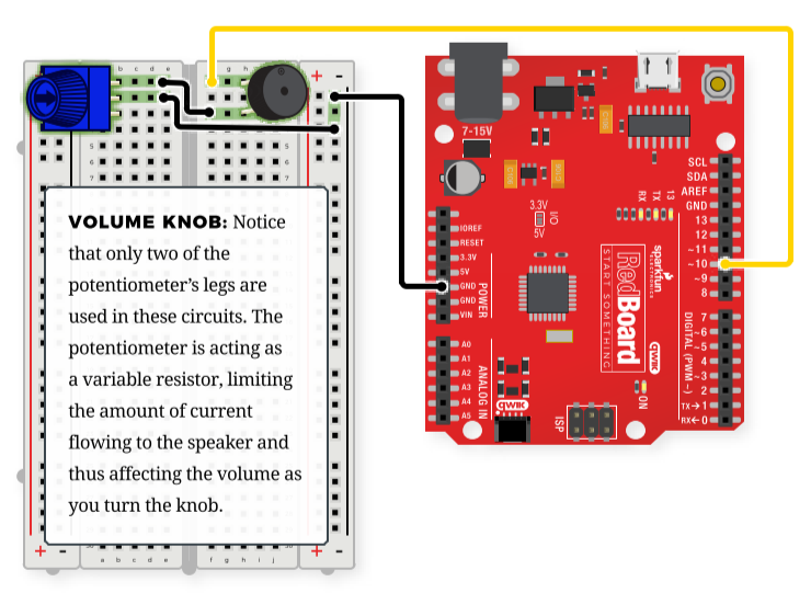
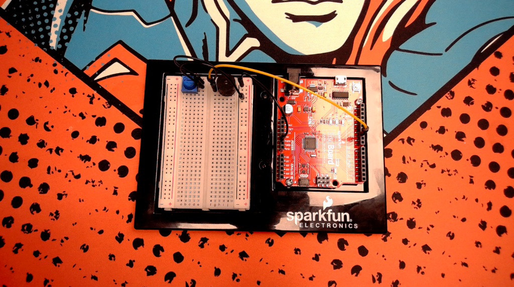
In this section we will use a trim-pot to control the volume of a buzzer
/*
  SparkFun Inventor’s Kit
  Circuit 2A - Buzzer
  Play notes using a buzzer connected to pin 10
  This sketch was written by SparkFun Electronics, with lots of help from the Arduino community.
  This code is completely free for any use.
  View circuit diagram and instructions at: https://learn.sparkfun.com/tutorials/sparkfun-inventors-kit-experiment-guide---v41
  Download drawings and code at: https://github.com/sparkfun/SIK-Guide-Code
*/
int speakerPin = 10;               //the pin that buzzer is connected to
void setup()
{
  pinMode(speakerPin, OUTPUT);    //set the output pin for the speaker
}
void loop()
{
  play('g', 2);       //ha
  play('g', 1);       //ppy
  play('a', 4);       //birth
  play('g', 4);       //day
  play('C', 4);       //to
  play('b', 4);       //you
  play(' ', 2);       //pause for 2 beats
  play('g', 2);       //ha
  play('g', 1);       //ppy
  play('a', 4);       //birth
  play('g', 4);       //day
  play('D', 4);       //to
  play('C', 4);       //you
  play(' ', 2);       //pause for 2 beats
  play('g', 2);       //ha
  play('g', 1);       //ppy
  play('G', 4);       //birth
  play('E', 4);       //day
  play('C', 4);       //dear
  play('b', 4);       //your
  play('a', 6);       //name
  play(' ', 2);       //pause for 2 beats
  play('F', 2);       //ha
  play('F', 1);       //ppy
  play('E', 4);       //birth
  play('C', 4);       //day
  play('D', 4);       //to
  play('C', 6);       //you
  while (true) {}     //get stuck in this loop forever so that the song only plays once
}
void play( char note, int beats)
{
  int numNotes = 14;  // number of notes in our note and frequency array (there are 15 values, but arrays start at 0)
  //Note: these notes are C major (there are no sharps or flats)
  //this array is used to look up the notes
  char notes[] = { 'c', 'd', 'e', 'f', 'g', 'a', 'b', 'C', 'D', 'E', 'F', 'G', 'A', 'B', ' '};
  //this array matches frequencies with each letter (e.g. the 4th note is 'f', the 4th frequency is 175)
  int frequencies[] = {131, 147, 165, 175, 196, 220, 247, 262, 294, 330, 349, 392, 440, 494, 0};
  int currentFrequency = 0;    //the frequency that we find when we look up a frequency in the arrays
  int beatLength = 150;   //the length of one beat (changing this will speed up or slow down the tempo of the song)
  //look up the frequency that corresponds to the note
  for (int i = 0; i < numNotes; i++)  // check each value in notes from 0 to 14
  {
    if (notes[i] == note)             // does the letter passed to the play function match the letter in the array?
    {
      currentFrequency = frequencies[i];   // Yes! Set the current frequency to match that note
    }
  }
  //play the frequency that matched our letter for the number of beats passed to the play function
  tone(speakerPin, currentFrequency, beats * beatLength);
  delay(beats * beatLength);  //wait for the length of the tone so that it has time to play
  delay(50);                  //a little delay between the notes makes the song sound more natural
}
/* CHART OF FREQUENCIES FOR NOTES IN C MAJOR
  Note      Frequency (Hz)
  c        131
  d        147
  e        165
  f        175
  g        196
  a        220
  b        247
  C        262
  D        294
  E        330
  F        349
  G        392
  A        440
  B        494
*/Project 2B: Digital Trumpet
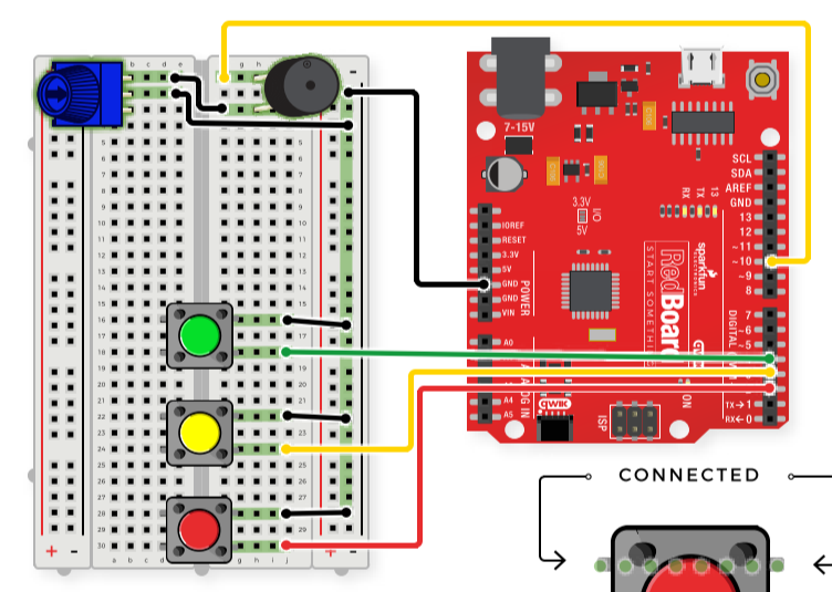
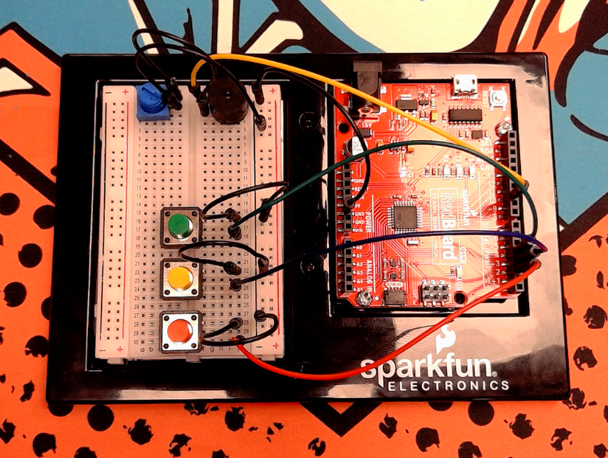
/*
  SparkFun Inventor’s Kit
  Circuit 2B-ButtonTrumpet
  Use 3 buttons plugged to play musical notes on a buzzer.
  This sketch was written by SparkFun Electronics, with lots of help from the Arduino community.
  This code is completely free for any use.
  View circuit diagram and instructions at: https://learn.sparkfun.com/tutorials/sparkfun-inventors-kit-experiment-guide---v41
  Download drawings and code at: https://github.com/sparkfun/SIK-Guide-Code
*/
//set the pins for the button and buzzer
int firstKeyPin = 2;
int secondKeyPin = 3;
int thirdKeyPin = 4;
int buzzerPin = 10;
void setup() {
  //set the button pins as inputs
  pinMode(firstKeyPin, INPUT_PULLUP);
  pinMode(secondKeyPin, INPUT_PULLUP);
  pinMode(thirdKeyPin, INPUT_PULLUP);
  //set the buzzer pin as an output
  pinMode(buzzerPin, OUTPUT);
}
void loop() {
  if (digitalRead(firstKeyPin) == LOW) {      //if the first key is pressed
    tone(buzzerPin, 262);                     //play the frequency for c
  }
  else if (digitalRead(secondKeyPin) == LOW) { //if the second key is pressed
    tone(buzzerPin, 330);                     //play the frequency for e
  }
  else if (digitalRead(thirdKeyPin) == LOW) { //if the third key is pressed
    tone(buzzerPin, 392);                     //play the frequency for g
  }
  else {
    noTone(buzzerPin);                        //if no key is pressed turn the buzzer off
  }
}
/*
  note  frequency
  c     262 Hz
  d     294 Hz
  e     330 Hz
  f     349 Hz
  g     392 Hz
  a     440 Hz
  b     494 Hz
  C     523 Hz
*/
If I was to take this project further, I would add the ability for multiple buttons to be pushed and to create modified tones. Right now, if multiple buttons are pushed ‘c’ takes precedence, then ‘e’ and finally ‘g’.
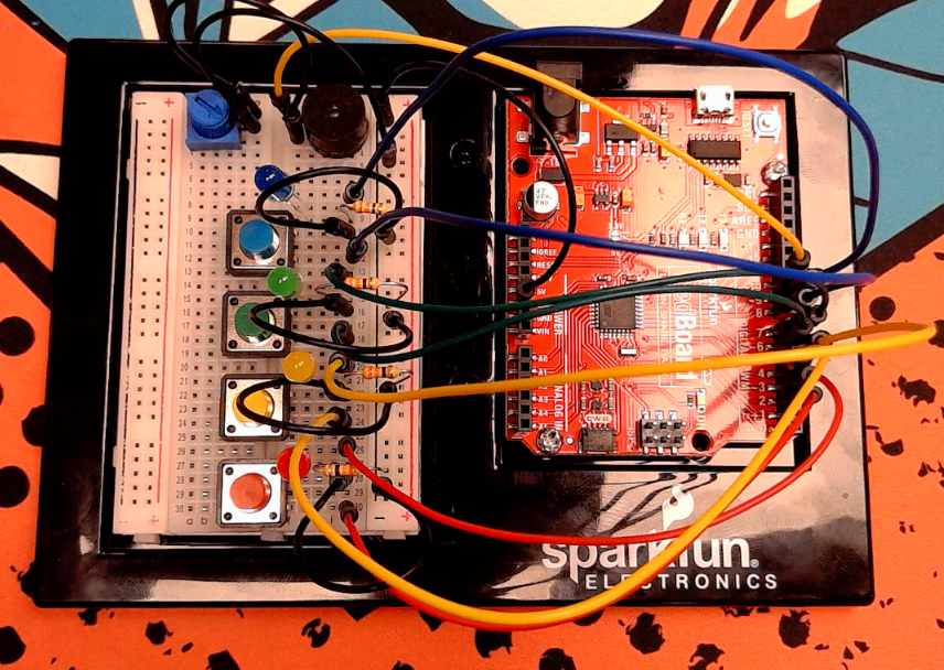
Project 2C: “Simon Says” Game
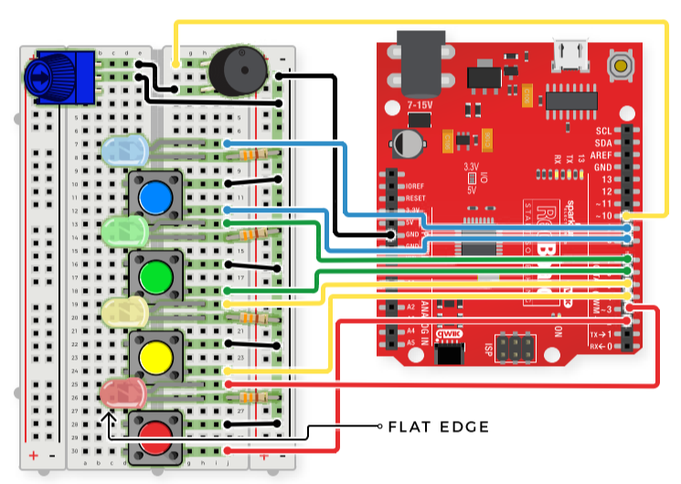
/*
  SparkFun Inventor’s Kit
  Circuit 2C-Simon Says
  The Simon Says game flashes a pattern using LED lights, then the player must repeat the pattern.
  This sketch was written by SparkFun Electronics, with lots of help from the Arduino community.
  This code is completely free for any use.
  View circuit diagram and instructions at: https://learn.sparkfun.com/tutorials/sparkfun-inventors-kit-experiment-guide---v41
  Download drawings and code at: https://github.com/sparkfun/SIK-Guide-Code
*/
//set the pins where the buttons, LEDs and buzzer connect
int button[] = {2, 4, 6, 8};  //red is button[0], yellow is button[1], green is button[2], blue is button[3]
int led[] = {3, 5, 7, 9};     //red is led[0], yellow is led[1], green is led[2], blue is led[3]
int tones[] = {262, 330, 392, 494};   //tones to play with each button (c, e, g, b)
int roundsToWin = 10;         //number of rounds the player has to play before they win the game (the array can only hold up to 16 rounds)
int buttonSequence[16];       //make an array of numbers that will be the sequence that the player needs to remember
int buzzerPin = 10;           //pin that the buzzer is connected to
int pressedButton = 4;        //a variable to remember which button is being pressed. 4 is the value if no button is being pressed.
int roundCounter = 1;         //keeps track of what round the player is on
long startTime = 0;           //timer variable for time limit on button press
long timeLimit = 2000;        //time limit to hit a button
boolean gameStarted = false;      //variable to tell the game whether or not to play the start sequence
void setup() {
  //set all of the button pins to input_pullup (use the built-in pull-up resistors)
  pinMode(button[0], INPUT_PULLUP);
  pinMode(button[1], INPUT_PULLUP);
  pinMode(button[2], INPUT_PULLUP);
  pinMode(button[3], INPUT_PULLUP);
  //set all of the LED pins to output
  pinMode(led[0], OUTPUT);
  pinMode(led[1], OUTPUT);
  pinMode(led[2], OUTPUT);
  pinMode(led[3], OUTPUT);
  pinMode(buzzerPin, OUTPUT);   //set the buzzer pin to output
}
void loop() {
  if (gameStarted == false) {   //if the game hasn't started yet
    startSequence();            //flash the start sequence
    roundCounter = 0;           //reset the round counter
    delay(1500);                //wait a second and a half
    gameStarted = true;         //set gameStarted to true so that this sequence doesn't start again
  }
  //each round, start by flashing out the sequence to be repeated
  for (int i = 0; i <= roundCounter; i++) { //go through the array up to the current round number
    flashLED(buttonSequence[i]);          //turn on the LED for that array position and play the sound
    delay(200);                           //wait
    allLEDoff();                          //turn all of the LEDs off
    delay(200);
  }
  //then start going through the sequence one at a time and see if the user presses the correct button
  for (int i = 0; i <= roundCounter; i++) { //for each button to be pressed in the sequence
    startTime = millis();                 //record the start time
    while (gameStarted == true) { //loop until the player presses a button or the time limit is up (the time limit check is in an if statement)
      pressedButton = buttonCheck();      //every loop check to see which button is pressed
      if (pressedButton < 4) {            //if a button is pressed... (4 means that no button is pressed)
        flashLED(pressedButton);          //flash the LED for the button that was pressed
        if (pressedButton == buttonSequence[i]) { //if the button matches the button in the sequence
          delay(250);                   //leave the LED light on for a moment
          allLEDoff();                  //then turn off all of the lights and
          break;                        //end the while loop (this will go to the next number in the for loop)
        } else {                          //if the button doesn't match the button in the sequence
          loseSequence();               //play the lose sequence (the loose sequence stops the program)
          break;                        //when the program gets back from the lose sequence, break the while loop so that the game can start over
        }
      } else {                            //if no button is pressed
        allLEDoff();                      //turn all the LEDs off
      }
      //check to see if the time limit is up
      if (millis() - startTime > timeLimit) { //if the time limit is up
        loseSequence();                       //play the lose sequence
        break;                                //when the program gets back from the lose sequence, break the while loop so that the game can start over
      }
    }
  }
  if (gameStarted == true) {
    roundCounter = roundCounter + 1;      //increase the round number by 1
    if (roundCounter >= roundsToWin) {              //if the player has gotten to the 16th round
      winSequence();                      //play the winning song
    }
    delay(500);                           //wait for half a second between rounds
  }
}
//----------FUNCTIONS------------
//FLASH LED
void flashLED (int ledNumber) {
  digitalWrite(led[ledNumber], HIGH);
  tone(buzzerPin, tones[ledNumber]);
}
//TURN ALL LEDS OFF
void allLEDoff () {
  //turn all the LEDs off
  digitalWrite(led[0], LOW);
  digitalWrite(led[1], LOW);
  digitalWrite(led[2], LOW);
  digitalWrite(led[3], LOW);
  //turn the buzzer off
  noTone(buzzerPin);
}
//CHECK WHICH BUTTON IS PRESSED
int buttonCheck() {
  //check if any buttons are being pressed
  if (digitalRead(button[0]) == LOW) {
    return 0;
  } else if (digitalRead(button[1]) == LOW) {
    return 1;
  } else if (digitalRead(button[2]) == LOW) {
    return 2;
  } else if (digitalRead(button[3]) == LOW) {
    return 3;
  } else {
    return 4; //this will be the value for no button being pressed
  }
}
//START SEQUENCE
void startSequence() {
  randomSeed(analogRead(A0));   //make sure the random numbers are really random
  //populate the buttonSequence array with random numbers from 0 to 3
  for (int i = 0; i <= roundsToWin; i++) {
    buttonSequence[i] = round(random(0, 4));
  }
  //flash all of the LEDs when the game starts
  for (int i = 0; i <= 3; i++) {
    tone(buzzerPin, tones[i], 200); //play one of the 4 tones
    //turn all of the leds on
    digitalWrite(led[0], HIGH);
    digitalWrite(led[1], HIGH);
    digitalWrite(led[2], HIGH);
    digitalWrite(led[3], HIGH);
    delay(100);         //wait for a moment
    //turn all of the leds off
    digitalWrite(led[0], LOW);
    digitalWrite(led[1], LOW);
    digitalWrite(led[2], LOW);
    digitalWrite(led[3], LOW);
    delay(100);   //wait for a moment
  } //this will repeat 4 times
}
//WIN SEQUENCE
void winSequence() {
  //turn all the LEDs on
  for (int j = 0; j <= 3; j++) {
    digitalWrite(led[j], HIGH);
  }
  //play the 1Up noise
  tone(buzzerPin, 1318, 150);   //E6
  delay(175);
  tone(buzzerPin, 1567, 150);   //G6
  delay(175);
  tone(buzzerPin, 2637, 150);   //E7
  delay(175);
  tone(buzzerPin, 2093, 150);   //C7
  delay(175);
  tone(buzzerPin, 2349, 150);   //D7
  delay(175);
  tone(buzzerPin, 3135, 500);   //G7
  delay(500);
  //wait until a button is pressed
  do {
    pressedButton = buttonCheck();
  } while (pressedButton > 3);
  delay(100);
  gameStarted = false;   //reset the game so that the start sequence will play again.
}
//LOSE SEQUENCE
void loseSequence() {
  //turn all the LEDs on
  for (int j = 0; j <= 3; j++) {
    digitalWrite(led[j], HIGH);
  }
  //play the 1Up noise
  tone(buzzerPin, 130, 250);   //E6
  delay(275);
  tone(buzzerPin, 73, 250);   //G6
  delay(275);
  tone(buzzerPin, 65, 150);   //E7
  delay(175);
  tone(buzzerPin, 98, 500);   //C7
  delay(500);
  //wait until a button is pressed
  do {
    pressedButton = buttonCheck();
  } while (pressedButton > 3);
  delay(200);
  gameStarted = false;   //reset the game so that the start sequence will play again.
}Robotics Primer Workbook – Robot Components
These exercise’s give us a chance to review the sensors for the SIK, and to review the various components that make up the SIK.
Robotics Primer Workbook – Exercise 1: Sensors and Sensor Space
- List each of the sensors in the SIK.
- Small Servo – Can detect stalls
- Ultrasonic Distance sensor – detects 2-400cm non-contact ranging
- TMP36 Temp Sensor – detects ambient temperature
- Photocell – detects ambient lighting
- Tactile buttons – detects contact
- 10k Trimpot – can be adjusted to adjust behavior
- Mini Power switch – can be adjusted to adjust behaviour
A sensor provides input from the environment to the robot. These devices allow the robot to react sense the world around them. I was debating whether to include the trimpot and the power switch in this list though as it requires manipulation to adjust, they don’t really change or adapt while the robot is operating independently. But, they are still a way that the external environment/factors can affect the robot so I have chosen to include them for now.
2. Define the SIK’s sensor space. For each sensor identify what the sensor perceives and the range of possible readings.
- Small Servo – stall detection, can detect if servo is unable to spin freely
- Ultrasonic Distance Sensor – collision, 2-400cm
- TMP36 Temp Sensor – temperature, -40C – 125C as a voltage between 2.7 – 5.5VDC
- Photocell – light level, 0-1023 analog input
- Tactile buttons – Contact, 0 or 1/ off or on digital input
- 10k Trimpot – dial, 0-1023 analog input
- Mini power switch – switch, 0 or 1/ off or on digital input
3. Now imagine a sonar sensor has been added to the SIK, what is the new sensor space?
I believe a sonar sensor would offer the same sensor range as the ultrasonic distance sensor. It would provide range or collision information.
Robotics Primer Workbook – Exercise 2: Effectors and Actuators
- Describe the difference between effectors and actuators
Effectors allow the robot to effect the world, they are the tools that allow movement and interaction. An actuator drives the movement of the effector. The actuators are the motors or hydraulics that power the robot.
2. List each of the SIK’s actuators and effectors
- Small Servo – actuator
- Hobby Gearmotor – actuator
- Wheels – Effector
3. List the degrees of freedom for the create.
I would say that the SIK has 3 degrees of freedom, as there are three actuators. If the parts were assembled into an arm, the two gear motors could be used to lift and swing the arm, while the small servo could rotate the arm.
Conclusion
I believe that completes my notes for Unit 1. I’m looking forward to Unit 2 soon.
Shawn Ritter
October 8th, 2021
Featured Image: https://www.nytimes.com/2018/11/12/obituaries/douglas-rain-dead.html

